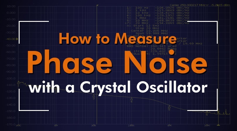
In a perfect world, a crystal oscillator would generate a signal that remains steady, consistent, and clear with no deviations, for as long as that signal needs to be transmitted.
But in the real world, no crystal oscillator produces a 100% perfect signal. Even if the signal is very strong and clear, there will still be tiny, random fluctuations in its waveform. This phenomenon can be represented visually in the frequency domain as sidebands on either side of the carrier. These unwanted fluctuations are referred to as phase noise.
In the blog, we'll explain why you need to measure phase noise, what the methods are for measuring it, and
Reasons for Measuring Phase Noise
It's important to be aware of phase noise because it's an indicator of how well the devices affected by it will perform. Systems affected by significant phase noise levels will experience poorer levels of performance. Some networks are more susceptible to phase noise than others.
Depending on the application, such as medical technology, GPS in military operations, etc., phase noise can not only be inconvenient, but also dangerous. If the noise is bad enough, there's also the risk of interference with adjacent channels, making it a problem for everyone and not just users of the crystal oscillator generating the noise.
Related: The Ultimate Guide to Understanding Phase Noise
Phase Noise Measurement Methods & Techniques
There are numerous methods for measuring phase noise, each with their own pros and cons.
Measuring Phase Noise with a Spectrum Analyzer
The default method in many cases is to use a spectrum analyzer. Anyone who works with RF technology is familiar with the oscilloscope, which observes and displays signals in the time domain, with the vertical axis representing voltage and the horizontal axis representing the signal over time.
A spectrum analyzer follows the same basic principle, but measures and displays a signal in the frequency domain instead, by showing the amplitude of a signal on the vertical axis and the frequency on the horizontal.
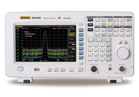
Spectrum analyzer
When using a spectrum analyzer, the device under test (DUT) is connected directly to the analyzer’s input. Phase noise is measured by the amount of noise within a specific bandwidth (traditionally 1Hz) relative to the carrier power. Measurements of phase noise are displayed as the number of dBc per Hz at a particular offset.
Spectrum analyzers are complex devices and are considered indispensable tools for testing in RF engineering. A good introductory guide into the specifics of how to use these devices can be found here.
Measuring Phase Noise with a Crystal Oscillator Using the Reference Source/Quadrature Method
When it comes to crystal oscillators, however, a spectrum analyzer alone may not be sufficient for measuring phase noise. Some high-performance oscillators produce noise at such low levels that it becomes difficult to accurately detect and measure it. One way around this problem is to use the reference source/quadrature method.
This method involves testing two oscillators set to the same frequencies. One is the DUT, the crystal oscillator having its phase noise measured. The second one will be an oscillator with superior performance, which will be the "reference source" against which the DUT will be compared. Their signals are combined with a mixer and fed through a low pass filter and a low noise amplifier (LNA). From there, the noise measurements can be taken with a spectrum analyzer or with a fast Fourier transform (FFT) analyzer.
If the input signals from both sources are adjusted to be in phase quadrature, the DC voltage output from the mixer will be zero volts. The resulting output from the mixer will provide a direct measurement of the phase difference between the crystal oscillator under test and the reference source, as long as the reference source is performing better than the DUT.
In some situations, a phase locked loop (PLL) with the reference source will have to be used in order to create a feedback system that maintains phase quadrature. But using a PLL can cause problems with system calibration, since it can remove low-frequency components from the mixer’s output. The phase noise measurements must be corrected mathematically to account for this, or the PLL must be set so that it is below the frequency offset.
A reference source/quadrature approach to measuring phase noise can be very effective, and by following best practices for this method, you can avoid most problems and gain accurate noise measurements for a crystal oscillator.
Related: The Secret to Low Phase Noise in Crystal Oscillator Circuits
Your Choice of Crystal Oscillator Is Important in Reducing Phase Noise
As the old saying goes, an ounce of prevention is worth a pound of cure. The best way to reduce phase noise as much as possible and improve performance in any application is to pick a well-designed crystal oscillator product in the first place.
With almost a century of experience in the industry, Bliley specializes in crafting the highest quality low and ultra-low phase noise crystal oscillators on the market. Explore our full line of high-performance crystal oscillators.