What's better than a crystal oscillator? A crystal oscillator combined with electronic frequency control (EFC)!
Of course, determining if EFC would be a good addition to your crystal oscillator circuit design (and if so, which method is best for you) comes down to your specific application and its requirements.
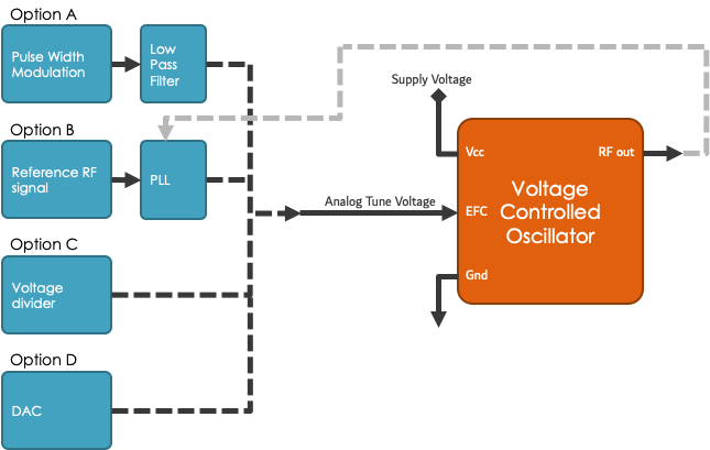
There are four options to choose from when selecting an electronic frequency control method for your crystal oscillator:
- Pulse width modulation (PWM) & low-pass filter (LPF)
- Reference RF signal & phase locked loop (PLL)
- Voltage divide
- Digital-to-analog converter (DAC)
In this post, we'll take a closer look at each option and their best applications.
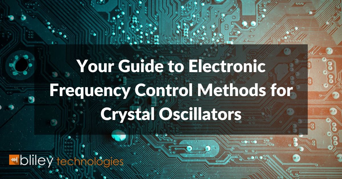
Option A: Pulse Width Modulation (PWM) & Low Pass Filter (LPF)
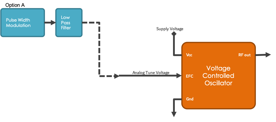
Pulse width modulation (PWM) is a way to control analog devices with a digital output. The signal can be varied to determine how long a signal is "high" in analog form. While a PWM can only be high (typically 5V) or low (ground) at a given time, you can adjust the amount of high vs. low time over a consistent time interval. This will allow you to achieve an average operating voltage that is emitted.
If the pulse is driven high 50% of the time, we call this a 50% duty cycle. The term duty cycle is used elsewhere in electronics, but in every case, duty cycle is a comparison of high vs low signals.
PWM can be used in quite a few applications, including sophisticated control circuitry. Its main use is for controlling DC motors, but it can also be used to control valves, pumps, hydraulics, and other mechanical parts.
Additionally, a low-pass filter (LPF) is commonly used to smooth the PWM output before it heads to a quartz crystal oscillator. A LPF will convert your PWM output into a voltage corresponding to the percentage of the PWM waveform.
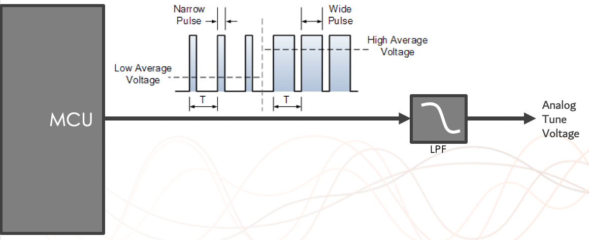
Option B: Reference RF Signal & Phased Locked Loop (PLL)
A reference RF signal is any outside reference frequency. This typically includes cesium, rubidium, or a superior performing crystal oscillator (also known as a master reference oscillator).
The reference RF signal is then sent to a phased locked loop (PLL). A PLL consists of three components:
- Phase detector (PD)
- Low-pass filter (LPF)
- Voltage-controlled oscillator (VCO)
Although phase detector is the common terminology, a PD is technically a phase difference detector. The PD accepts two periodic input signals and produces an output signal that represents the phase difference between the two.
That output is then transferred to the low-pass filter. Since the output from the PD isn't a straightforward analog signal that's proportional to the phase difference, the LPF helps eliminate unnecessary high frequencies and transforms the signal into an output that controls a voltage-controlled oscillator (VCO).
In a VCO, the output frequency of the oscillator is precisely controlled by a voltage. This means that the VCO is a variable-frequency oscillator that allows an external voltage to influence its frequency of oscillation. In a PLL, the external voltage comes from the PD and LPF.
Related: How Does a VCXO Work?
Option C: Voltage Divider
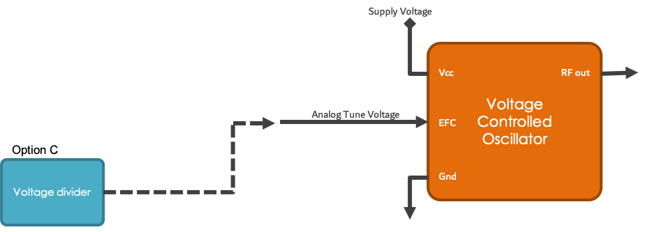
A voltage divider is a simple circuit that turns a large voltage into a smaller one. You can use just two series resistors and an input voltage to create an output voltage that is a fraction of the input. Voltage dividers are considered to be one of the most fundamental electronic circuits.
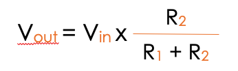
You can use the voltage divider equation to determine the output of a voltage divider. For this equation you'll need to know:
- Input voltage (Vin)
- Both resonator values (R1 and R2)
Being one of the most fundamental circuits, voltage dividers are used in many applications. Some common ones include potentiometers, sensors, and level shifters.
While there are almost endless applications for voltage dividers, they should not be used as a load's power supply.
Option D: Digital-to-Analog Converter (DAC)
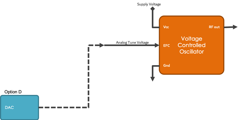
Simply put, a digital-to-analog converter (DAC) converts digital signals into analog signals. There are many DAC architectures that are suitable for different applications. These designs are determined by metrics such as resolution and the maximum sampling frequency.
Digital-to-analog conversion can degrade signals, so a DAC should be specified that has very little errors in terms of the application.
The most specialized DACs are implemented as integrated circuits (ICs) because of the complexity and the need for precisely matched components. Discrete DACs would typically be extremely high speed, low resolution, power hungry types, as used in military radar systems. Very high speed test equipment, especially sampling oscilloscopes, may also use discrete DACs.
Related: 7 Key Factors of Crystal Oscillator Circuit Design
Selecting the Best EFC Method for Your Application
We hope this brief overview has given you a good idea of which method would work best for your application. Have additional questions? Reach out to our team to discuss the needs of your project.