
There are 7 key factors to understanding successful crystal oscillator circuit design. These include:
- Series circuit
- Crystal load capacitance
- Parallel circuit
- Drive level
- Frequency vs. mode
- Design considerations
- Negative resistance
What Is a Crystal Oscillator Circuit? (Oscillator Circuit Basics)
Crystal oscillator circuits consist of an amplifier and a feedback network. The feedback network takes specific output from the amplifier and sends it back to the amplifier input. It looks pretty simple when drawn out...
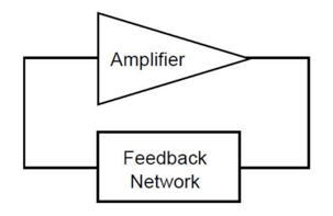
... but there's a lot more complexity the deeper we go. Hold on tight!
Two critical conditions must be met for a crystal oscillator circuit to operate effectively:
- The loop power gain must be equal to unison.
- The loop phase shift must be equivalent to 0, 2Pi, 4Pi, etc. radians.
The power directed back to the input of the amplifier must be enough to supply the amplifier input and oscillator yield, and to overcome circuit losses.
The precise frequency of an oscillator is determined by the loop phase shifts within the oscillator circuit. Any change to the phase shift will result in a change in frequency. One of the best ways to reduce net phase shift is to use a quartz crystal in the feedback loop. All of the crystals we manufacture here at Bliley include quartz crystals (quartz crystal oscillators).
Related Read: Understanding the Types of Crystals Inside of Your Oscillators
When a quartz crystal is used in the feedback loop of an oscillator, the frequency output of the oscillator actually regulates itself. The quartz crystal creates a reactance which satisfies the phase loop requirements.
Now that you have a solid understanding of the basics of crystal oscillator design, let's jump into the key considerations for crystal oscillator circuit design.
7 Key Considerations for Crystal Oscillator Circuit Design
1. Series Circuit
A series circuit crystal oscillator uses a crystal that's designed to operate at its natural resonant frequency. There's no need for capacitors in the feedback loop for this type of circuit. Series resonant oscillator circuits are fairly basic and are typically used because of their small component count.
The series circuit may provide feedback paths other than through the crystal. This means that the circuit may continue to oscillate at a subjective frequency even during a crystal failure.
A significant downfall to the series circuit is that you cannot adjust the output frequency if the system requires modification. A series resonant crystal is designed to the preferred frequency, tolerance, and stability, and holds without option for adjustment.
2. Load Capacitance
Load capacitance can play a critical role in oscillator circuit design. You'll see an example of the importance of load capacitance in the next design consideration, but for now, let's take a closer look at load capacitance itself.
Load capacitance is described as the amount of capacitance measured or computed across the crystal terminals in the circuit.
When it comes to the series circuit, there's no capacitance between the connecting points of the crystal circuit. Therefore, there's no load capacitance in the circuit. It's a different story with parallel circuits.
To determine load capacitance in a parallel circuit (described in design consideration #3), use this handy equation:
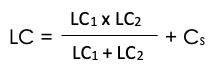
In this equation, LC1 and LC2 represent the load capacitors. Cs is the circuit vagrant capacitance (usually between 3 and 5 pF).
3. Parallel Circuit
A parallel resonant oscillator circuit is made with a crystal that's designed to operate with a specific load capacitance. This causes a crystal oscillator to operate with a frequency that's higher than the series resonant frequency but lower than the true parallel resonant frequency.
To complete the feedback loop in this type of circuit, you must design routes through the crystal. If the crystal fails, the circuit will no longer oscillate.
So where does the load capacitance come from that determines the oscillator's frequency? This circuit actually uses a solitary inverter with two capacitors in the feedback loop that encompass the load capacitance. If the load capacitance is changed, so will the frequency produced by the oscillator.
With that being said, it's important to note that this circuit type is not ideal for easily adjusting frequency if required. Also, exact frequency control and precise specification of load capacitance is required.
For example, if a 20 MHz crystal with a capacity of 20 pF is placed in a circuit with an assessment of 30 pF, the crystal will be lower than the specified value. But if the circuit has an assessment of only 10 pF, the frequency will be higher than the specified value.
4. Drive Level
The drive level is the amount of power consumed by the crystal while in operation. Power is typically described in terms of milliwatts or microwatts.
Quartz crystals are specified to a maximum value of drive level that can influence the frequency and the mode of operation of the oscillator. It's important to work with your crystal oscillator vendor to determine the maximum drive level that can be sustained by the quartz oscillator.
So what happens if a crystal oscillator exceeds the maximum drive level? It could cause the oscillator to:
- Become unstable
- Speed up age rates
- Cause loss of communication or timing in critical applications
To calculate drive level of a crystal, use this equation (basically just Ohm's Law, but for power):
Drive Level = (Irms2 x R)
In this equation, Irms is the measured RMS current through the quartz crystal and R is the maximum resistance of the quartz crystal.
To measure the actual drive level of a crystal oscillator circuit, you can insert a resistor into it. The voltage drop across the resistor can then be read to calculate the current and power dissipation. Of course, make sure you remove the resistor after this measurement.
5. Frequency vs. Mode
A crystal oscillator's frequency can be restricted by physical dimensions. Sometimes, this might be the length and width for certain applications. Other times, it may be the thickness of the quartz crystal itself. The thinner the quartz wafer, the higher the frequency will be. The thickness of the quartz wafer typically becomes too thin for processing around the 30 MHz level.
If you need an oscillator with a frequency higher than the limiting frequency, you can take advantage of fundamental frequencies. A fundamental frequency is defined as "the lowest frequency which is produced by the oscillation of the whole of an object, as distinct from the harmonics of higher frequency." If a crystal has a fundamental frequency of 10 MHz, it can also oscillate at 3, 5, 7, etc. times the fundamental frequency. Therefore, the oscillator can oscillate at 30 MHz, 50 MHz, 70 MHz, etc. These are the frequency's overtones.
When use of an overtone frequency is needed, a crystal manufacturer must design the crystal to operate at the desired overtone frequency. Never try to order a fundamental mode crystal and then operate it at another desired overtone because crystal manufacturing processes are different for fundamental and overtone crystals.
Related Read: Common Misconceptions About Oscillator Frequency Stability
6. Design Considerations
A handful of design considerations should be followed for best oscillator circuit operation. One thing that's always recommended is that parallel traces be avoided in the circuit. Doing so will reduce stray capacitance. All traces should be kept as short as possible to prevent coupling. Keeping components isolated by using ground planes can also help with this.
7. Negative Resistance
An oscillator must be designed to enhance negative resistance for best performance. Negative resistance is also frequently called oscillation allowance.
Here are six simple steps to help you calculate negative resistance in an oscillator circuit:
- Temporarily install a variable resistor in series with a crystal.
- Set the resistor to the lowest setting (close to zero ohms).
- Power up the oscillator and monitor the output on an oscilloscope.
- Begin to increase the resistance in the circuit using the variable resistor as you continually monitor the oscilloscope signal.
- As soon as the oscillation comes to a stop, take note of the variable resistor to determine the ohmic value.
- Add the maximum resistance value of the crystal (specified by the vendor) to the ohmic value measured in step 5.
This total value calculated is the negative resistance or oscillation allowance. For a general rule of thumb, the negative resistance should be a minimum of 5x the specified maximum resistance value of the crystal to be reliable.
Quartz Crystal Oscillators That Will Take Your Next Project Further
Bliley Technologies has been designing and manufacturing crystal oscillators for almost a century. Browse our full line of frequency products to find one that fits your project's needs, or contact our engineers today to learn more.