
Surface acoustic wave (SAW) filters offer a reduced size, weight, and cost compared to other filter technologies. There are many tradeoffs, however, that need to be considered when selecting a SAW filter for your system design.
What are SAW filters? What are some common SAW filter applications? How are SAW filters used for mobile communications? We'll answer these questions and more in this post.
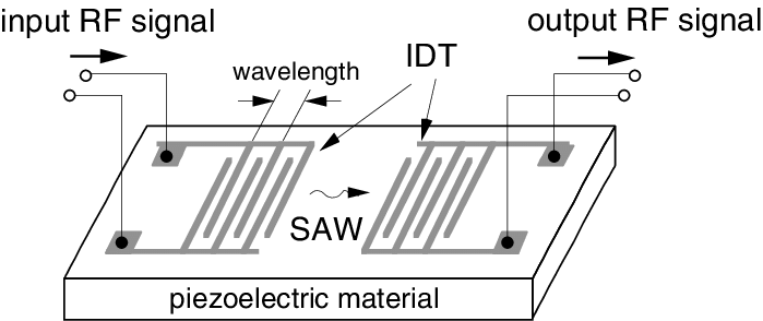
SAW filter diagram
What Are SAW Filters?
A SAW filter is an electronic device that converts electrical energy into acoustic or mechanical energy via a piezoelectric material. This process occurs using two interdigital transducers: input and output transducers.
- The input transducer creates acoustic waves from the incoming electrical signal.
- The output transducer receives these acoustic waves and converts them back to electrical energy.
The transducers create a bidirectional transversal filter. That's because the frequency waves are produced equally in the -X and +X directions. The wave produced by the output transducer is only 1/2 of the full. So, if a loss of 3dB is observed from the output wave, that means the total signal from the input and output transducer has an insertion loss of 6dB.
Each transducer is made up of periodic interdigital electrodes connected to two bus bars that connect to the electrical source (or load).
The amplitude will be determined by the electrode length and the phase by the electrode position. The wavelength of the electrodes determines the operating frequency of the SAW filter.
7 Most Common Piezoelectric Materials Used for SAW Filters
| Material | Velocity (m/s) | Temp. Coefficient (ppm/°C) | Coupling Coefficient (K2) | Application |
| YZ Lithium Niobate |
3488 |
94 | 0.045 | Wide band filters, long delay time and delay lines |
| 128º Lithium Niobate | 3992 | 74 | 0.055 | wide band filters |
| Quartz | 3158 | -0.033 ppm/oC2 | 0.00116 | Narrow band filters, short delay lines, resonators |
| 112º Lithium Tantalate | 3290 | 18 | 0.0075 | Mid band filters |
| 41º Lithium Niobate | 4792 | 50 | 0.172 | Low loss filters |
| 64º Lithium Niobate | 4792 | 70 | 0.113 | Low loss filters |
| 42º Lithium Tantalate | 4022 | 40 | 0.076 | Low loss filters |
Temp. Coefficient (ppm/°C): The shift in center frequency vs. the operating temperature of the SAW filter.
Coupling Coefficient (K2): How efficient the material is at producing an acoustic wave. A larger K2 means stronger acoustic waves and typically less loss per unit of delay.
Here at Bliley Technologies, we specialize in manufacturing quartz SAW filters. As you can see in the table above, quartz SAW filters are great for narrow band filters, short delay lines, and resonators. If you think a quartz SAW filter may suit your application, contact us and we can help you find the best option.
Anyway, on with the show...
When Standard SAW Filters Won't Cut It: Low Loss SAW Filters
There may be situations and applications when standard filter performance might not cut it. In these cases, a lower loss and smaller size filter may be required.
There are multiple design options that are available to help meet application needs that can not fully be met with standard SAW technology. These include:
- SPUDT filters
- Ring filters and IIDT filters
- IEF resonator filters
- Coupled resonator filters (CRF and TCRF)
Single Phase Unidirectional Transducer (SPUDT) Filters
Reducing amplitude of the SAW in the -X direction increases the SAW in the +X direction. This is done by utilizing reflector electrodes in the transducers. SPUDT can provide great narrowband low loss filters; however it may not be best for wideband filters. A fan transducer (slanted or tapered transducer) can help create wider bandwidth with lower loss.
Ring Filter and IIDT Filters
Ring filters use 2 transducers in different coupled tracks and are coupled by reflecting track changers. This transfers SAW from one track to the other.
IIDT filters use a sequence of identical IDTs that are connected to the output and input ports. The output transducers receive identical input waves from both sides. This converts the SAW info into electrical output.
The same goes for the output transducers; however, some loss will occur because the SAW will still flow to the crystal ends that require dampening.
Impedance Element Filter (IEF) Resonator Filter
An IEF filter is designed with parallel and series elements arranged to achieve a specific filter shape. This is done by taking advantage of the resonance characteristics of each element type.
IEF filters are great for:
- Large bandwidths
- Higher center frequencies
- Small size
- Greater input power options
Coupled Resonator Filters (CRF and TCRF)
For many applications, coupled resonator filters (CRF) can be designed using either wide or narrow bandwidths and low loss. CRF filters are based on single and two-pole configurations.
A transverse-coupled resonator filter (TCRF) is made up of resonators that are connected electronically to make up a narrow band filter. Filters using two or more resonators are acoustically coupled transversally within the device.
What's the Difference Between SAW and BAW Filters?
SAW and BAW (bulk acoustic wave) technologies are similar in many ways. They both emit acoustic waves but in different ways and at different performance levels (especially at higher frequencies). But don't get them confused! They also have many differences.
In a SAW component, acoustic waves travel across the surface of a piezoelectric material with amplitude that usually decays exponentially into the substrate material. In contrast, acoustic waves in a BAW filter travel through and are stored in the piezoelectric material itself.
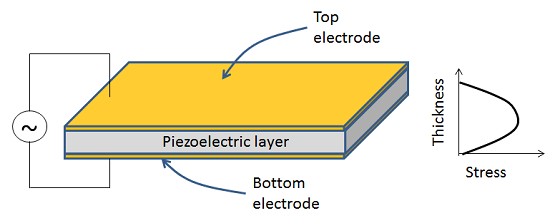
BAW filter diagram
Even though SAW and BAW technologies act differently, they can be very complementary to each other. SAW filters can be designed to about 2.0 or 2.5 GHz before the SAW transducer becomes unmanageably small. BAW filters can be used for 2.7 GHz and beyond for filtering, delay lines, and other functionality.
These differences in frequency make SAW and BAW filters make the perfect duo in many applications including long-term evolution (LTE) wireless communications where lower and higher frequency bands are required.
Common SAW Filter Applications & Industries
Industries that commonly use SAW filter technology include:
- Mobile communications & telecommunications
- Medical
- Radar
- Military & aerospace communications
Let's take a deeper look into how these industries are using SAW filters in specific applications.
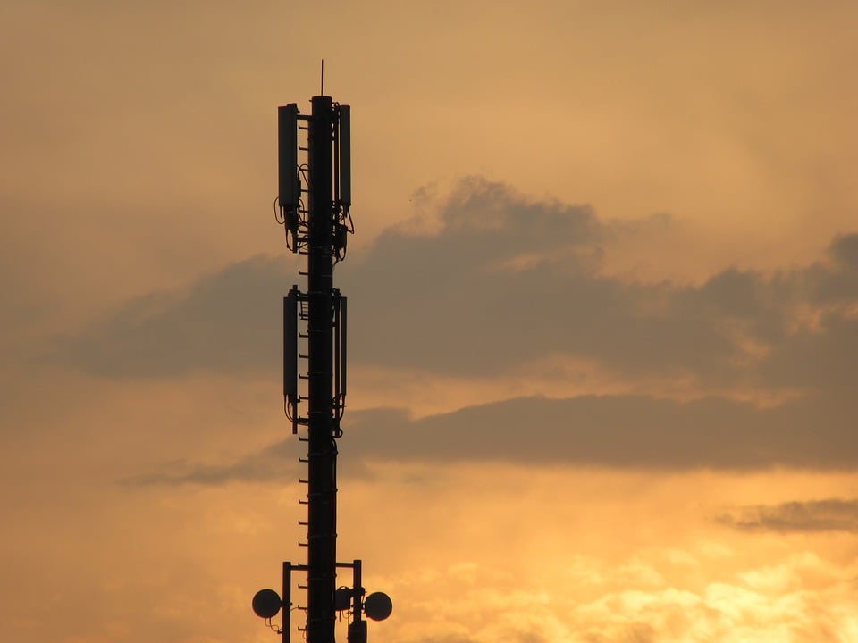
Mobile Communications & Telecommunications
SAW filters work great in many telecommunication applications all thanks to their small size, light weight, and durability. They are the most common filter type for mobile communications devices and are typically used up to the 2GHz bandwidth.
Specific applications that commonly use SAW filters within mobile communications include:
- LTE bands (long-term evolution)
- 5G
- GSM (Global System for Mobile Communications)
- CDMA (code-division multiple access)
- WCDMA (wideband CDMA)
As for telecommunications, SAW filters are frequently used in base stations as bandpass filters in the IF stage. The amplitude here will ideally have low-distortion and minimal passband variation.

Medical
SAW Filters can also be ideal for many different applications within the medical industry. One of the most common uses is for sensors. Sometimes medical applications use a SAW delay line as a sensor element for in-situ detection.
A more practical application includes using SAW filters as bandpass filters for wireless communication in the medical industry. These typically include low power, near field communications.
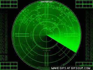
Radar
SAW Filters that possess a linear delay change over a set pass bandwidth are great for radar solutions. This is also known as time bandwidth (TB). The larger the time bandwidth, the better the locating and tracking effectiveness. The tracking can be even more effective by adding a digital signal processor.
Active electronically scanned array (AESA) radars are among the newest and most popular radars today. They're also a great application for SAW filters. The AESA can direct radio waves into different directions without moving the antenna itself. It can even send out multiple radio wave beams at multiple frequencies simultaneously. This technology is used in today's ships and aircraft for radar spoofing.

Military & Aerospace Communications
SAW filters can be designed to provide high selectivity and low distortion for military communication & aerospace applications. They also help provide a lower cost and size compared to other filter technologies.
SAW filters can also provide band pass filtering for many military & aerospace communication needs including:
- Transmitter and receiver filters
- Intermediate frequency (IF) filters in superheterodyne systems
- IF filters in software defined radios (SDR)
- Identification Friend or Foe (IFF) applications
Related: Check out these 11 Innovative Military and Electronic Warfare tech blogs
SAW Technology also works as a great combo with duplexers and could be used for local oscillators in many other military communication needs.